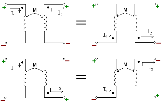
As a reminder, mutual-inductance indicators ("dots") demonstrate how the common-mode choke suppresses high frequency common-mode currents by generating an opposing/canceling current for each entering line (imagine two equal current pulses both entering in the same direction, each one generating a corresponding pulse through mutual inductance that suppresses the other line's pulse in a kind of cross-cancellation)
High frequency differential noise is shunted across lines by the "X"-style capacitors and high frequency common-mode noise is shunted to chassis/ground by the "Y"-style capacitors (Class X and Y are based on safety capacitors types but I'm using them here to describe their connection configuration).
This document illustrates the difference well.
A discussion on Capacitive (Electric-Field) and Inductive (Magnetic Field) coupling (causes of interference) follows the break.
In Capacitive Coupling a voltage between two conductors separated by dielectric/insulator (e.g. air, FR4 PCB) can create a parasitic capacitance that will pass/couple high frequency signals.
In Inductive Coupling, changes in current cause changing magnetic fields which in turn can induce currents in nearby conductors:
- Current in a conductor generates a magnetic field oriented around it based on the right-hand rule/Ampere's Law
- Time-varying currents therefore result in time-varying magnetic fields
- Time-varying magnetic fields induce a voltage (emf - Electromotive Force) (and correspondingly a current if the medium is a conductor) in accordance with Faraday's Law
- Based on Lenz's Law, the emf is generated such that the magnetic field created by the induced current OPPOSES the inducing magnetic field. By the right-hand rule this means for parallel conductors the induced current with be travelling opposite to the inducing current (i.e. an increasing clockwise field is opposed by creating a counter-clockwise field - a decreasing clockwise field is opposed by creating a clockwise field)
Here is a link with further illustration.
No comments:
Post a Comment